
Welcome to my model train Blog. (2017)

I am presently building an HO scale Digital Command Control (DCC) model train layout.
I installed an HO scale (120') foot Diamond Scale model train turntable.
Also look at the other (2) below shown procedures.
Diamond Scale Model Train Turntable (2017 - Add A Sound Module)
(2017 - Add A Sound Module) <<< (Mouse Click To Link)
Diamond Scale Model Train Turntable (2017 - Turntable Motor)
(2017 - Turntable Motor) <<< (Mouse Click To Link)

Advanced Turntable Indexing Controls
There are some very advanced electronic hardware suppliers that will index model train turntables (100%) perfectly every time. This requires special costly ($'s) hardware and special costly ($'s) software.
#1) Stepper motor for a model train layout turntable.
#2) Special coupler to attach stepper motor to turntable rotating shaft.
#3) Required hardware to mount the stepper motor.
#4) Special electronic programmable circuit board to control the stepper motor.
#5) Any type of stepper motor can not be used with any type of sound module.
A very advanced PTC: Model 4 is a totally self-contained fully programmable circuit board costing ($495.00). This does not include a stepper motor or required mounting hardware.
There is also the Arduino Uno Rev.3 a micro controller circuit board that will control a stepper motor ($28.00). But this requires a computer to operate and special computer programming software to control a stepper motor.

I took early retirement and was a highly skilled tool-maker. (+/- .0005"). To achieve almost perfect indexing at (0') degrees and (180') degrees at the same indexing (#) location, the (2) rotor arm wiper pads center contact must be located directly in the center of the turntable track
at both ends.


There is a term called, stack up of all components tolerances. Each different component has it's own (+/-) tolerance. Add up all the different components (+/-) tolerances and you will have the have the actual final (+/-) tolerance of the finished assembled component. It is almost impossible to have the turntable track exactly in the center (x & y) rotating locations.
There are (4) main determining factors.
(#1) True center line (x) location of clamping bushing metal glued onto the throw arm.
(#2) True center line (x) location of turntable wooden swing arm with metal verticle axle.
(#3) True center line (x & y) locations of turntable pit hole.
(#4) True center line (x) location of turntable track at both (2) ends.

When indexing the turntable, (1) end of the track will align perfectly, while the opposite end
will not align perfectly.


Modifying the lower rotor arm to operate much more accurately:
MLR Products no longer exists and it used to manufacture many different types of special track laying tools. Micro-Mark bought out MLR Products. (https://www.micromark.com/Deluxe-HO-Gauge-Track-Laying-Set). Micro-Mark has a (Deluxe HO Gauge Track Laying Set) (Item #: 84114) that has the required track laying tool (Flex Track Alignment Tool). But you are required to purchase the complete, only [HO] gauge track laying set. For perfect alignment of the turntable track at both (2) ends, a (Flex Track Alignment Tool) is the ideal tool. But this tool is no longer available to be purchased as a separate required track laying tool. It is also only available in [HO] gauge.
Make your own track alignment tool for any model train gauge. Use a small flat square wooden block (6") inches long. Make sure that the wooden block sits flat onto the rail ties by filing (2) chamfers on the bottom face. Glue on required layer card (shims) for required inner track width. Layer card material is thin hard cardboard like cereal boxes.

The turntable will require a master end turntable location. If the turntable has a small shed, it will indicate the master end turntable location. If the turntable does not have a small shed, some special type of permanent identification on the turntable will be required at this turntable end location.
Index the turntable to the (#1) indexing master end position on the layout. You may be required to slightly jog the turntable that may also turn "off" the LED . Place the alignment tool to clamp into location the (#1) indexing location. With a red marker color the vertical shaft and locking bushing.
The master end turntable location is marked with Green Dots on the rotor arm and wiper pad.
On the opposite end mark with Red Dots on the rotor arm and wiper pad. This next procedure requires a lead pencil. Along both sides of the rotor arm, mark out (2) lines onto the bottom of the wooden box. Use a (3/64") allen hex key and carefully remove the rotor arm.

The Green Dots on the rotor arm and wiper pad will remain the same. Only the Red Dots on the rotor arm will be modified. De-solder the (3) wires soldered to the rotor arm. Totally remove the wiper pad. Scribe (2) center lines for starting point references. Use a small "round" and a small "flat fine metal files to elongate the (2) mounting clearance holes. Elongate the (2) holes a minimum of (2) times the hole size. Replace the wiper pad roughly in the center location and do not tighten down the (2) mounting screws. These (2) screws will require future adjustment. Re-solder the (3) wires to the rotor arm.

Since you have the rotor arm off, this would be a good time to remove any oxidisation from the thin (6) brass contacts on the (2) wiper pads. Use machinist 320 or 400 fine sandpaper and very lightly polish the (6) contacts. When the rotor arm was removed from the vertical shaft, the set screw in the locking bushing left a burr. With a small flat smooth file, remove any burr left behind on the vertical shaft. Using the sensor wooden blocks under the turntable are only bottom glued into place. This is not a strong permanent clamping procedure. There is a very likely chance that a glued on wooden sensor block will break off in the following procedures.
#1) With a thin permanent black marker, mark out all (4) sides of all sensor blocks.
#2) Also (#) each individual wooden sensor block, the indexing (#) location.
#3) Use a good epoxy glue and add a good bead of glue to all (4) sides of the sensor wooden blocks.
Using a hot wax gun for glue, will result in a soft rubbery support. I read an article that Gorilla (LA) epoxy glue works quite well with wood. When using any type of epoxy glue, there is the "maximum setting time" and the "minimum curing time" to fully dry correctly.

For all sensor blocks to function exactly the same, all the contact points should be set at the same height. Make a small wooden block to make a (Master Height Block).. Since the top and bottom faces will not be parallel, cut out a notch to only allow for a (1/2" x 1/2") datum face. If required, glue on required layer card (shims) for best required average height. Layer card material is thin hard cardboard like cereal boxes. Under the sensor contact wiper is a long dimple. Using the master height block, slightly bend all sensor contact wipers so they are all at the same height.

Will be re-installing the long rotor arm only having a small clamping bushing. Must insure that both (2) wiper pads on the rotor arm are at the same height so all sensor blocks operate exactly the same. Will require (2) set blocks to insure that both (2) ends of the wiper pads are at the same height.

Each and every different model turntable will have a different (Master Height Block)..
Calculations are required to insure that both (2) wiper pads are at only 1/8" inch (.125") contact pressure offset.
(A) = Master Height Block
(B) = Distance from the bottom of the sensor wiper to the top contact point 3/32" (.09")
(C) = Offset pressure distance between contact point and wiper pads 1/8" (.125")
(D) = Required calculation
(E) = Height of wiper pad
(F) = Assembly height using (2) set blocks
Required Calculations:
#1) Add (A) height + (B .09") = (AB) dimension.
#2) Subtract (AB) dimension - (C .125") = (D) dimension
#3) Add (D) dimension + (E) height wiper pad height = (F) dimension
The (F) dimension is the requited height for the (2) set blocks.

Recommend using (3/4" x 1 1/2") "finish pine" strip.
The (2) small wooden set blocks must be flat on the bottom face.
The (4) round head screws will allow for height adjustment and to be parallel to each other.
The (2) set blocks are cut in (1/2) to allow for easy removal from inside the inner channel.

Procedures:
(#1)
Cut (2) wooden blocks to (F) dimension minus 1/2" (.50").
On a hard flat surface, using a sheet of fine sandpaper, sand both (2) top and bottom faces flat and smooth.
(#2)
Will be using (#10-16) x 3/4" length round head sheet metal screws.
Drill (4) 3/32" (.094") Dia. pilot holes into the (2) set blocks 3/4" (.75") deep.
(#3)
Mark a horizontal (black) height center line on both (2) blocks.
Identify the wooden blocks (1) and (2) above and below the center line.
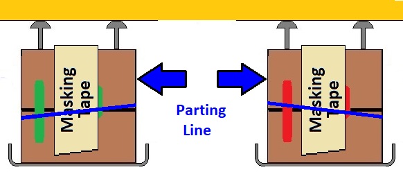
On Block (1) with a green marker, color in a square box just above the center line and only (1) vertical line on the left side. On Block (2) with a red marker, color in a square box just above the center line and only (1) vertical line on the left side. Now carefully cut the (2) wooden blocks in (1/2). On a hard flat surface, using a sheet of fine sandpaper, sand all (4) cut faces flat and smooth.
(#4)
Install the (4) screws allowing for an extra plus 1/2" (.50") height.
(#5)
Lay the (2) matching sets onto a flat smooth surface. Using masking tape, tightly wrap the (2) matching sets together. Press down the masking tape on all (4) sides of the (2) matching sets to insure adhesion. Now using a sharp exacto knife, cut (2) sides of each matching set to remove the masking tape from the bottom face.
(#6)
The (2) set blocks must be parallel to each other. Also retaining the required (F) dimension.
(#7)
By exchanging the matching faces, back and forth, will check for parallelism between the (2) wooden blocks. Adjust the (4) screws to achieve total parallelism and required (F) dimension.

The Diamond Scale front control panel has a green (5.MM) LED that will light up to only indicate that indexing has fully stopped. To make it much easier to correctly align the wiper pad and the wiper pad add a (2nd) extended (5.MM) LED to the indexing circuit board, directly under the turntable for easy viewing. Make sure that the turntable circuit board is not powered when adding the (2nd) LED. Also be sure to get a wide angle viewing (5.MM) LED. Diffused LED's have the widest viewing angle. Also replacing the front control panel LED with a new diffused green (5.MM) LED.


In a previous procedure, on both sides of the rotor arm, (2) lines were marked out using a lead pencil. This is to make re-assembly much easier and more accurate. Will be using (2) rubber bands to hold the rotor arm into place while re-mounting. Using (4) short length (1/2") cup hooks to hold the required rubber bands. Draw (2) new parallel lines (1/2") from the marked out (x2) Lines
using a lead pencil. Locate (4) locations dots where the (4) cup hooks will be only temporarily mounted. Cup hooks come with different wood screw thread sizes without describing the actual thread size.
(#6) wood screw 9/64" (.140") = pilot drill 5/64" (.078")
(#8) wood screw 5/32" (.156") = pilot drill 3/32" (.094")
Drill the (4) required pilot drill holes. Mount the (4) cup hooks. Have (1) rubber band hanging from (2) hooks on the back side.

The turntable circuit board must be powered ON. The turntable front panel rotary switch must at indexing location (#1). Mount rotor arm with green dot wiper pad over sensor block (#1).
Wrap the (2) rubber bands to secure the rotor arm. If required, add more rubber bands to insure that the (2) set blocks are sitting flush to the top face. Adding too much tension using too many rubber bands may make it more difficult to move the rotor arm. Adjust the rotor arm so the center contact on wiper pad comes into contact with the sensor block (#1). This will cause the green (5.MM) LED to light up. Now tighten down the set screw, clamping the rotor arm into place. Do not be concerned if the LED goes off. Using a sharp exacto knife, cut off all the rubber bands. This will prevent any undo extra stress pulling off the rubber bands manually. Using a sharp exacto knife, carefully cut the masking tape on the (2) mating faces of the (2) set blocks. Since the (2) mating faces of the (2) set blocks are not at a perfect (90'), the set blocks will separate much more easily in a certain direction. Now carefully slide out the (2) top half's of the set blocks having the screws. Remove the (2) bottom half's of the set blocks.
If the LED is not on, only adjust the (#1) sensor block contact using (2) clamping screws till the LED remains on.
--> Remove the alignment tool from the turntable.
Procedures for all remaining green dotted indexing locations.
Only using the green dotted wiper pad end.
#1) Turntable front panel, rotary switch to next (#) indexing location.
#2) Turntable front panel, jog turntable to required next (#) indexing location.
#3) Place the alignment tool to clamp the turntable into location for this indexing location.
#4) Under the turntable, only adjust the sensor block contact using the (2) clamping screws.
#5) Till the LED remains on.
#6) --> Remove the alignment tool from the turntable.
Repeat the same above (6) procedures for all remaining indexing locations.

Only using the red dotted wiper pad end.
#1) Turntable front panel, rotary switch to (#1) indexing location.
#2) Turntable front panel, index and jog turntable to (#1) (180') indexing location.
#3) The red dotted wiper pad is over sensor block (#1).
#4) Place the alignment tool to clamp the turntable into location for this indexing location.
#5) Under the turntable do not adjust the (#1) sensor block contact using (2) clamping screws.
#6) Only adjust the red dotted wiper pad location, till the LED remains on.
#7) Carefully tighten down the (2) clamping screws on the red dotted wiper pad.
#8) --> Remove the alignment tool from the turntable.
Do not repeat any of the above (9) procedures for all remaining indexing locations.

Direct e-mail contact only regarding my Blogs: gtrs.trains@gmail.com
Posted by Grand Trunk Railway Systems at Dec. 03 2017